流路の形を変えるたび、また設計図から?
生成AIでマイクロ流路の試作を効率化する
小さな水路に液体を流し、混ぜたり分けたりする「マイクロ流路」。新しい装置を開発するときには、流路の幅や形を少しずつ変えて、何度も作り直す必要があります。問題は、そのたびに設計図を直し、3Dプリンタで製作し、寸法を確かめなければならないことです。
本研究の着眼点:設計図を速く作るだけでなく、実物を測って次の設計を改善する。
01 何が問題なのか? ―― 設計図と実物は簡単には一致しない
例えば、Y字に分かれる流路の幅を変えたいとします。CADで図面を修正し、3Dプリントして、顕微鏡で寸法を測ります。結果が狙いと違えば、また最初からやり直します。
一つの形を作るだけでも時間がかかる
606–799秒今回調べた3種類の流路をAutoCADで手動作図したときの平均時間です。
最初から正しい形になるとは限らない
中実化・位置ずれ初期のAI生成コードでは、水が通るはずの空間が埋まったり、分岐がずれたりしました。
CADが正しくても、印刷すると寸法がずれる
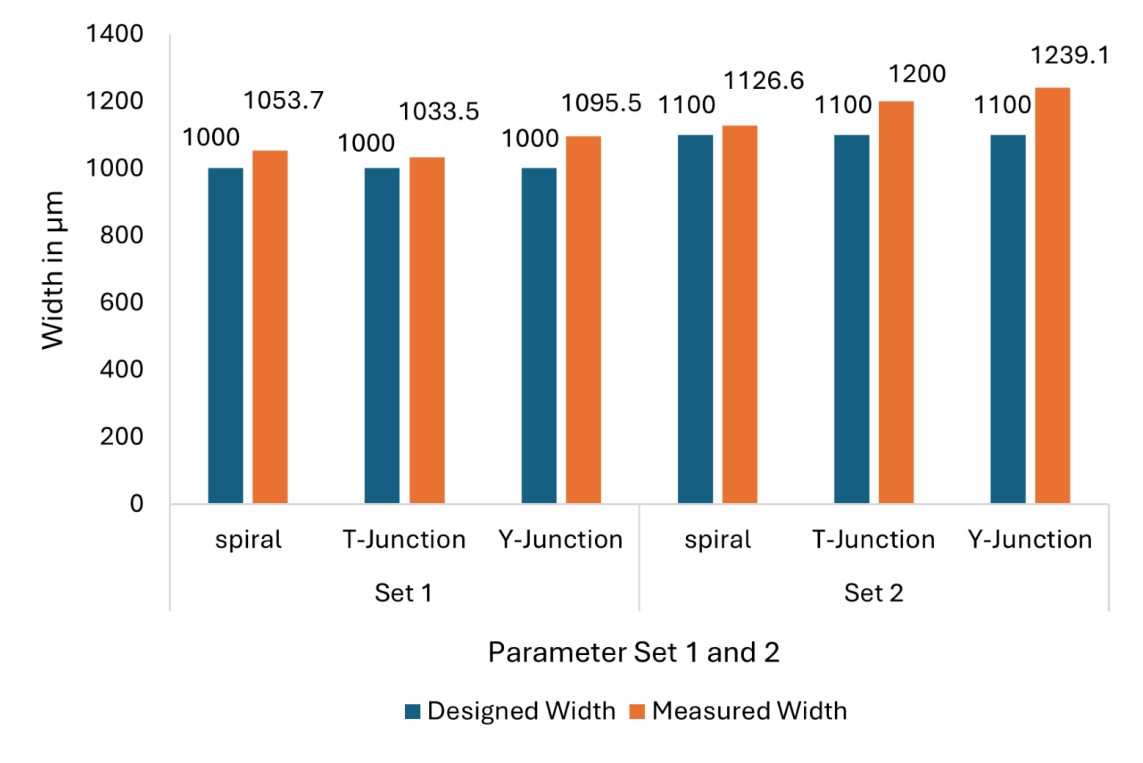
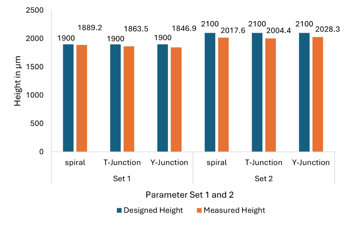
最大12.6%3形状・2組の条件で製作した流路トラックの外形幅には、最大12.6%のずれがありました。
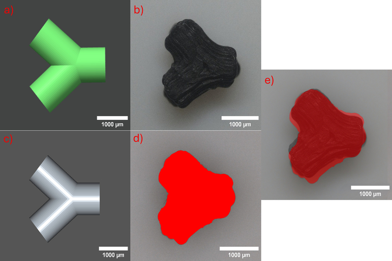
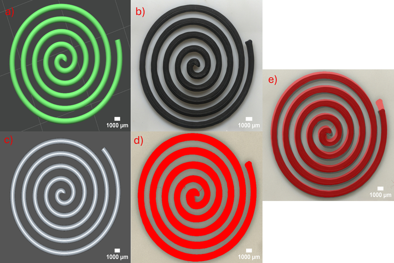
設計値は1,000 µm。完成品を測ると1,095.5 µm。
右の写真は、Y字流路のCADデータと3Dプリントした実物です。設計した流路トラックの外形幅は1,000 µm(1 mm)でしたが、造形後の平均値は1,095.5 µm。約9.6%広くなりました。
どの段階でずれたのかを見つけ、次の試作を改善できないだろうか?
02 どう解決したのか? ―― ChatGPTでコードを作り、Pythonで何度も設計する
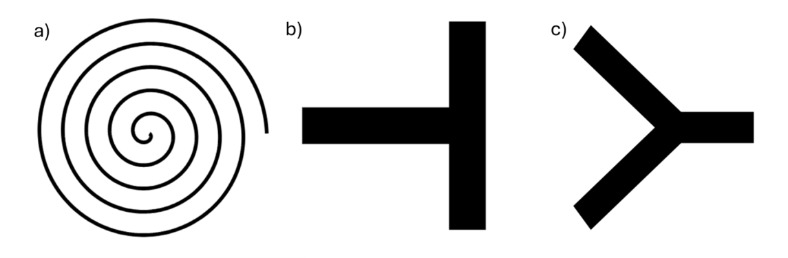
生成AIには、流路の形や寸法を伝えて設計用のPythonコードを書いてもらいます。そのコードを確認・修正して保存し、以後は流路幅や角度などの数字を変えるだけで図面を作り直します。
なぜPythonのコードを保存するのか?
同じ文章をChatGPTに入力しても、毎回同じコードが返るとは限りません。一方、確認済みのPythonコードを同じ条件で動かせば、同じ設計データを作れます。AIにはコードを書かせ、確定したコードで設計を繰り返す、という役割分担です。
ハッシュ値は「ファイルの指紋」。 確定したPythonコードを各形状で3回実行したところ、3回ともSTLファイルのMD5ハッシュ値が一致しました。つまり、同じ設計データが生成されたことを確認できました。
03 どれくらい速くなったのか? ―― 条件変更後の図面を数秒で出力
一度プログラムを完成させれば、幅、曲率半径、分岐角度、渦巻きの巻き数などを数字で指定して、別の設計条件をすばやく試せます。
| 流路形状 | 確定したPythonコードの実行 | AutoCADの手動作図 |
|---|---|---|
| Spiral mixer(渦巻き) | 0.80秒 | 799秒 |
| T-junction(T字) | 1.87秒 | 606秒 |
| Y-junction(Y字) | 4.32秒 | 692秒 |
論文Table I。各形状につき3回測定した平均。Pythonは完成済みスクリプトの実行開始から図面・STLの出力完了まで、手動CADは作図開始からSTL出力完了までを測定しました。
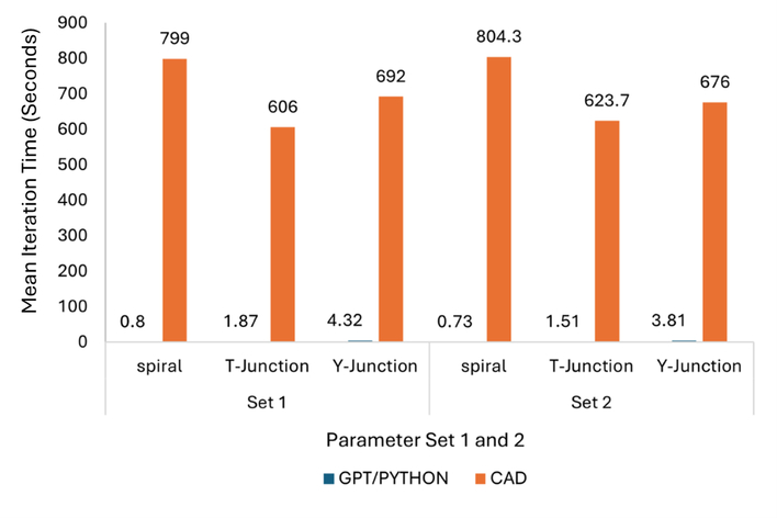
最初のコード作成にはChatGPTとのやり取りが必要で、対話による開発作業は合計約45~60分でした。完成後は、条件を変えるたびに一から作図する必要がなくなるため、複数条件の比較や繰り返し試作で効果を発揮します。
04 作った流路は狙った寸法だったのか? ―― 測定結果から補正する
図面ができても、完成品の寸法が合わなければ実験には使いにくくなります。そこで、設計データを確認したあと、FDM方式の3Dプリンタで製作した流路を顕微鏡で測定しました。
実際に測ることで、設計と造形の問題を切り分けた
まずSTLデータの寸法をMeshLabで確認し、指定した形状が出力されていることを調べました。その後、3Dプリントした流路の外形寸法をデジタルマイクロスコープで測定。ずれの主な発生場所が造形工程にあることを確認しました。
測定値を次の設計に戻すと、寸法のずれが小さくなった
| 流路形状 | 補正1回目の外形幅偏差 | 補正2回目の外形幅偏差 |
|---|---|---|
| T字 | +7.60% | +5.6% |
| Y字 | +8.57% | +4.8% |
論文Table IV。数値は補正1回目と2回目の比較です。3DプリンタはBambu Lab A1、材料はPLAを使用しました。
水を流す試験では、全デバイスで10 µL/minまで目視による漏れはありませんでした。漏れ始めた流量は渦巻き流路が15 µL/min、Y字が30 µL/min、T字が35 µL/minでした。形状が作れることに加え、実際に流れるかも確かめたことがポイントです。
この研究が実現したのは、設計図を繰り返し生成し、実物を作り、測定結果を次の設計に戻す、一連の試作工程です。
Redrawing a microchannel every time you change its shape?
Making microfluidic prototyping faster with generative AI
Microfluidic devices guide tiny amounts of liquid through narrow channels to mix, split, or direct a flow. Developing a new device means adjusting channel widths and shapes, then making and testing many prototypes. Each change can lead to another round of CAD drafting, 3D printing, and dimensional measurement.
Our idea: generate design files quickly, then use measurements of the physical device to improve the next design.
01 What makes prototyping difficult? — A CAD drawing and a printed device do not always match
Imagine changing the width of a Y-shaped channel. You revise the CAD model, print a new device, and inspect its dimensions under a microscope. When the result differs from the target, you repeat the cycle.
Even one geometry takes time to draw
606–799sMean manual AutoCAD drafting time for the three geometries tested in this study.
Initial AI-generated geometry can contain errors
Solid channels & misalignmentEarly scripts produced solid interiors instead of hollow channels, or misaligned junctions.
Correct CAD dimensions can still change during printing
Up to 12.6%Maximum deviation in overall channel-track width across three geometries and two parameter sets.
Designed width: 1,000 µm. Measured after printing: 1,095.5 µm.
The figure on the right compares CAD models with fabricated Y-junction devices. The target overall channel-track width was 1,000 µm (1 mm). The mean printed width was 1,095.5 µm — approximately 9.6% wider.
Can we identify where the deviation occurs and use that information to improve the next prototype?
02 Our approach — ChatGPT writes the code; Python generates repeatable CAD files
We give the language model the channel type and target dimensions, then use it to develop Python code. After checking and refining the code, we keep the finalized script and adjust numerical parameters such as width and angle to regenerate the design.
Why save and reuse the finalized Python script?
Identical prompts to ChatGPT can generate different code. A checked and finalized Python script, executed under the same conditions, generates the same design files. The LLM helps write the program; the fixed program reproduces the CAD geometry.
A hash is a file’s digital fingerprint. For each geometry, three executions of the finalized script yielded STL files with matching MD5 hashes. This confirmed that the design files were identical across repeated runs.
03 How much faster? — Regenerate a design in seconds
Once the script is ready, changes to channel width, curvature, junction angle, or spiral loop count can be entered as parameters. The updated CAD files are exported within seconds.
| Channel geometry | Finalized Python script | Manual AutoCAD drafting |
|---|---|---|
| Spiral mixer | 0.80 s | 799 s |
| T-junction | 1.87 s | 606 s |
| Y-junction | 4.32 s | 692 s |
Paper Table I; mean of three runs per geometry. Python times cover execution of the finalized script through file export. Manual CAD times cover drafting through STL export.
Developing the initial script took approximately 45–60 minutes of interactive work with ChatGPT. Once created, that script eliminates the need to redraw every variation from scratch, making it especially useful when comparing many design conditions or repeating fabrication cycles.
04 Did the printed channels meet the target dimensions? — Measure, then correct
A fast CAD model is useful only when the manufactured device can be evaluated against its target. We verified the digital geometry, fabricated channels by fused deposition modelling (FDM), and measured the printed devices using digital microscopy.
Measurements separate geometry generation from printing errors
We first checked the STL dimensions in MeshLab, then measured the fabricated channel-track dimensions under a digital microscope. This comparison showed that the dimensional deviations arose primarily during FDM fabrication.
Using measurements to update the next CAD design reduced width deviations
| Channel geometry | 1st compensated iteration | 2nd compensated iteration |
|---|---|---|
| T-junction | +7.60% | +5.6% |
| Y-junction | +8.57% | +4.8% |
Paper Table IV. These values compare the first and second compensated iterations. Devices were fabricated using PLA on a Bambu Lab A1 printer.
Flow testing showed no visible leakage up to 10 µL/min. Leakage began at 15 µL/min for the spiral mixer, 30 µL/min for the Y-junction, and 35 µL/min for the T-junction. The study tested not only whether the geometry could be generated, but also whether the printed channels carried fluid.
The outcome is a repeatable prototyping workflow: generate CAD, fabricate a device, measure the result, and use that measurement to improve the next design.